ZBasic System Library
ZBasic Microcontrollers
6
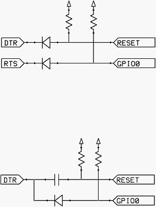
Auto Reset Mode
In this reset mode, the DTR signal is connected to the RESET pin (either directly or via a diode) while the
RTS signal is connected to GPIO0 (again, either directly ore via a diode). An example circuit for this
mode is shown below.
DTR Only Reset Mode
In this reset mode, the DTR signal is connected to the RESET pin via a diode and also connected to
GPIO0 (either directly ore via a diode). This is useful with some types of USB-Serial adapters that do not
break out the RTS signal. An example circuit for this mode is shown below.
Wifio Reset Mode
This is another reset mode that is useful when RTS is not available. Here, the DTR signal is connected to
RESET via a capacitor and GPIO0 is held low via a transistor by transmitting a serial break, effectively
holding the TxD line (the RxD input to the ESP8266) low for a period of time, typically about 250mS. The
simpler alternative shown second below seems to work just as well.